Lego Technic Tutorials & Concepts
| Lego Technic | Tutorials & Concepts | Sample Creations | Type of Components |
|---|
Alignment rule of stud and studless pieces
The basic rule of alignment for studless and studded pieces: Holes in two bricks separated by two plates are exactly 3 studs apart. This trick shows how bricks with plates can be repeated at regular intervals to align with beams. For example, in order to have a 5-stud-long space between their pin holes, two bricks need to be spaced apart by seven plates, by a brick and four plates, or by two bricks and one plate, as one brick is three plates tall.

Keeping the gears in place
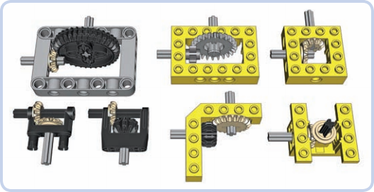
Reinforcing perpendicular bevel gears is a more difficult task, as even a minimal displacement in structure disengages the gears. This is because their teeth come into contact over a small area. We need to make sure the gears are firmly kept in place. A number of LEGO studfull and studless pieces are designed specifically to reinforce perpendicular gears. When you have no dedicated LEGO pieces to reinforce perpendicular gears, you can still use basic pieces to do so.
Differences between worms and regulars
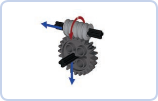
Unlike regular gears, a worm gear doesn’t push the follower gear to the side; instead, it pushes itself against the follower gear along its axle. Worm gears need particularly solid reinforcement. As the image beside the description shows, apart from pushing the follower gear away, worm gears have a strong tendency to slide along the axle they’re sitting on. This is a result of worm gears’ enlarged axle holes, which allow them to slide along axles. This lateral force can be strong enough to make a worm gear drill through adjacent pieces if sufficiently high torque is applied to it for a prolonged time!
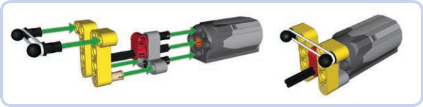
Return to center steering
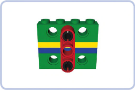
The rubber band–based return-to-center steering attachment for a PF Medium motor. The mechanism consists of the band (white), which squeezes two beams (yellow) together to the sides of a connector sitting on the steering shaft (red). As the motor starts to rotate the shaft, the connector pushes the beams apart. If the rubber band is strained enough, it will stop the connector quickly, and when the motor stops, it will squeeze the beams back together, returning the connector and the shaft to the central position.
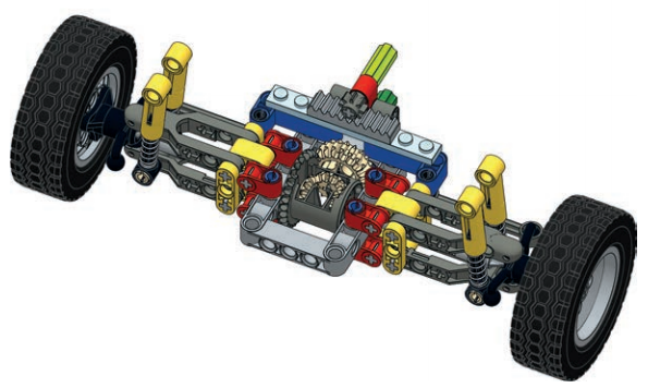
Transferring power to steering axles
A driven axle is a mechanism that connects two wheels while transferring drive to them from the chassis. The power is usually received from a driveshaft that is longitudinal to the chassis and perpendicular to the axle. Connecting these two elements is necessary, and a pair of bevel gears is the simplest solution. But in practice, bevel gears are prone to skipping under high torque, and a driven axle is where we can expect high torque. This leaves us with two other options: a differential or a pair of knobs. A differential is less likely to skip, especially if braced inside a proper structure.
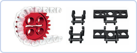
Chains and placement on gears
A close-up view of the chain wrapped around a gear shows that each link occupies two teeth. The section of the chain that has contact with the gear has no play in it, and its elasticity is minimized. The chain link (left) is similar to the LE GO track link (right) and can be combined with it. The chain consists of small, rigid links that can be connected so that every link can be tilted relative to the next one. In this way, we can create a flexible but rigid chain of any length, which can be wrapped around gears.
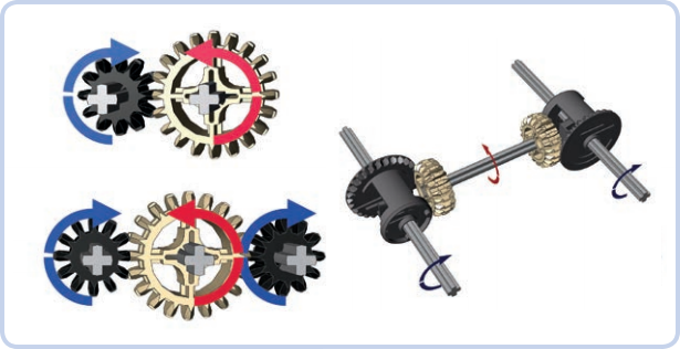
Linear and perpendicular gear directions
An even number of meshed gears (left) and an odd number of meshed gears (right). When gears are meshed directly, the driver gear affects the follower gear’s direction of rotation. Whether the follower rotates in the same or in the opposite direction as the driver depends on the number of gears between them. When gears are in a parallel series, the rule is simple: With an even number of gears (2, 4, 6, and so on), the follower rotates in the opposite direction, and with an odd number of gears (3, 5, 7, and so on), the follower rotates in the same direction. Direct observation may be the quickest means of determining the output rotation of gears that mesh perpendicularly. For example, in a 4×4 vehicle’s drivetrain with a longitudinal driveshaft, the front and real differentials must be oriented in opposite directions for the front and rear wheels to rotate in the same direction.